

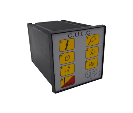
C.U.L.C
C.U.L.C. COMPUTERIZED UNIVERSAL LUBRIFICATION CONTROL
Compliant with current regulations
This electronic equipment has been developed to control and to check lubrification circuits for machine tools.
This is the only device that carries out the required functions by means of a microprocessor and thanks to this. It can offer very high functonality and reliability performances.

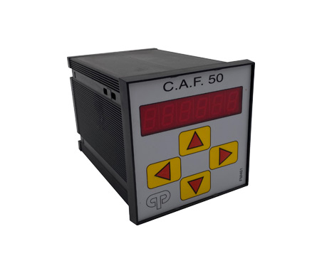
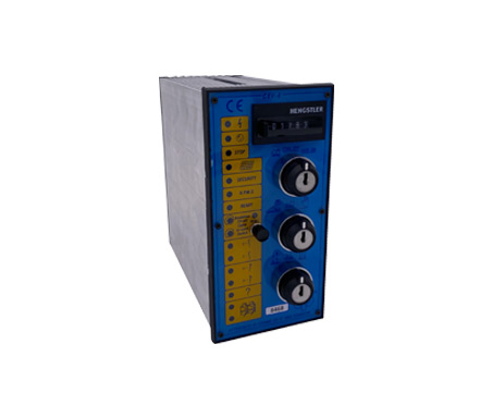
This device is made in a container according to the DIN41700 rules having a
front size of 96×96 mm.

The envelope is in NORYL (General Electric) with UL94V0 self-estinguishing specifications and with a good resistance to lubricants.
The front panel is made up by a membrane push-button panel with touch actuated RESET key.

LEDS are of a high efficiency type to have the best visibility even in overlighted rooms and the keyboard surface is in POLYESTER resisting to wear solvents and lubricants.

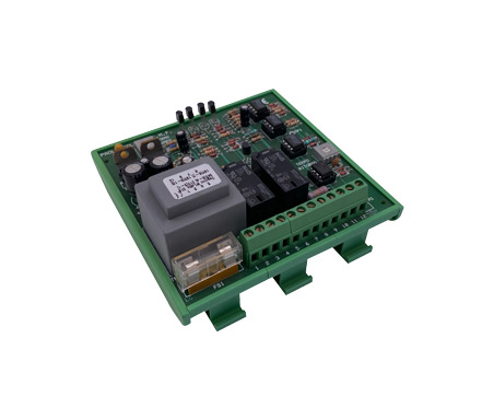
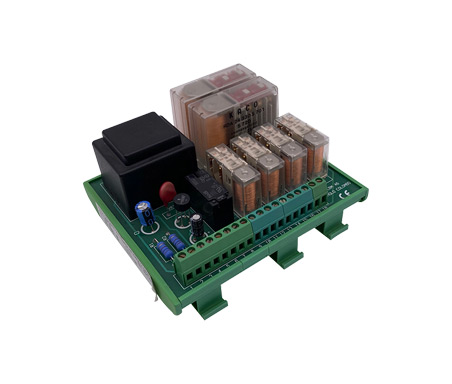
The extractable terminal boards for the connection to the system and the five selectors that can be actuated by means of a screwdriver n order to set the functions, are placed on the back of the container.

The plant can work in THREE MODES (MODE selector) 1 = STROKES, 2 =TlME, 3 = CONTlNUOUS
Strokes mode
(MODE selector on position 1)
On the “STROKES NUMBER” selectors set the number of machine cycles that will be the interval between two lubrication cycles.
On the “ALARM” selector set the time the lubrication cycle is to be terminated.
Warning that the time set is in seconds and is equal to the number displayed on the commutator multiplied bv twentv. The machine cycle calculation is increased by an external signal (CAM).
The contact Ml/1-2 starting the lubrication cycle closes when the count reaches the set value (STROKES NUMBER) The “P” LINE END PRESSURE SWITCH opens, thus stopping the lubrication cycle.
If the line end pressure switch remains open (the lubricant does not flow) or it the lubrication cycle does not take place within the expected alarm time (thecontact of the line end pressure switch does not open) the contact Ml/3-4 opens: this contact may be used to stop the machine or to advise the alarm condition. It is relevant to know that even when the machine is standstill. This operation mode being on. a lubrication cycle
automatically takes place every 45 minutes.
Example: MODE = 1
(lubrication connected with the cycles made by the machine)
STROKES NUMBER = 1 2 5 that is one lubrication cycle every 125 machine cycles.
When setting 0 0 0 machine cycles. Contact Ml/3-4 opens thus causing the alarm.
ALARM = 4 (x20) = 80 seconds. within this time the line end pressure switch must open. When setting 0 on ALARM selector the maximum time for the lubrication cycle, that is 200 seconds, is set.
Time mode
(MODE selector on position 2)
On the “TIME SECS x 10” selectors set the number of machine cycles that represents the interval between two lubrication cycles.
Warning: the time set s in seconds and is equal to the number displayed on the commutators multiplied by ten (therefore 999 corresponds to 9990 secs).
On the “ALARM” selector set the time. the lubrication cycle is to be terminated within.
Warning: the time set is in seconds and is equal to the number displayed on the commutator multiplied by twenty.
An internal CLOCK counts the time and when the fixed time is reached (TIME SECS x 10) the contact Ml/1-2 startings the lubrication cycle closes.
The “P” LINE END PRESSURE SWITCH opens thus stopping the lubrication cycle.
If the line end pressure switch remains open (the lubricant does not flow) or if the lubrication cycle does not take place within the expected alarm time (the line end pressure switch does not open), the contact Ml/3-4 opens; this contact may be used to stop the machine or to advise the alarm condition
Example: MODE = 2
(lubrication at time intervals.)
TlME SECS x 10=1 2 0 (xl0) that is one lubrication cycle every 1200 seconds (20 minutes). When setting 0 0 0 seconds. contact Ml/3-4 opens. thus causing the alarm. ALARM = 3 (x 20) = 60 seconds within this time the ne end pressure switch must open
When setting 0 on the ALARM selector the max mum time tor the lubrication cycle, that is 200 seconds, is set.
Continuous mode
(MODE selector on position 3)
In this case the equipment supervises a self-governing lubrication system which sends a certain number of lubrication impulses towards the machine in a fixed time.
Lubrication impulses are counted by means of an electrical signal connected to the “CAM” inlet and the overseeing device checks if the number of irnpulses sent in the fixed time unit is equal or higher than expected.
In this is lower, the alarm contact Ml/3-4 opens; this alarm contact may be used to stop the machine ot to advise an alarm.
The impulse number is set on the “STROKES NUMBER” selectors, while the time, the lubrication impulses must be delivered within, is to be set on the “ALARM” commutator.
Warning: the time set is in seconds and is equal to the number displayed on the commutator multiplied by twenty.
The +12V limit switch output is protected from short circuits. The end of line signal and the cam signal can come either from PNP or NPN inductive limit switches or from mechanical limit switches (+12V common). If a NO minimum level is used (closed when oil is missing), jump terminals 11 and 16.
Example: MODE = 3
(supervision of an external system of continuous lubrication.)
STROKES NUMBER = 0 2 0 that is 20 lubrication impulses within the fixed period of time.
When setting 0 0 0 impulses, contact Ml/3-4 opens/ thus causing the alarm.
ALARM = 3 (x 20) = 60 seconds, (it is typical to use the minute as reference unit for tirne).
When setting 0 on the ALARM selector, the maximum reference time for impulse counting is set.
As far as the wiring diagram is concerned please refer to the enclosure where you can also find some useful technical notes.
Symbols shown on the membrane keyboard are according to the ISO R369 rules and represent the following functions from the top to the bottom and from the eft to the right: feeding voltage available cam contact, pump temperature relay intervention, fault lubrication in course, Iine end pressure switch intervention, insufficient lubricant level.
The RESET push button clears the alarm singals provided that all the causes which originated the alarm have been removed.
Every time the key RESET is operated and every time FEEDING is applied to the equipment. if the LINE END PRESSURE SWITCH is CLOSED ( in MODE 1 and 2). A LUBRICATION CYCLE WILL TAKE PLACE.
On the contrary. if the LINE END PRESSURE SWITCH is OPEN, no LUBRICATION WILL BE DELIVERED and the FAULT LED will LIGHT UP.
NOTWITHSTANDING THIS THE ALARM CONTACT REMAINS CLOSED.
If the condition of the lubr cation system s RE-ESTABLISHED before the first automatic lubrication cycle, THE MACHINE WILL NOT STOP ITS OPERATION, OTHERWHISE the ALARM contact will open.
Technical data:
Voltage: 110 – 220 V 50 Hz
Relay contacts 250 Vac 10 A
Consumption: 2 VA
Inlets: 12 Vdc
Check out our catalog
STANDARD PRODUCTS
CONTACT US
For any information, question or request for collaboration you can contact us from the contact form.
Our Customer Service will be happy to answer your questions.
[contact-form-7 id=”5″ html_class=”cf7_custom_style_1″]