
CEV 4
CEV 4 BRAKE/CLUTCH COMMAND AND CONTROL MODULE
CONTROL UNIT FOR MACHINES EQUIPPED WITH BRAKE/CLUTCH ENGAGEMENT OPERATED BY MEANS OF DOUBLE SOLENOID VALVE
Compliant with current regulations
Approval IMQ n. AS 060 DM
CEV 4 modules must be regularly inspected at least once a year by an expert. The inspection must be carried out on all components.

This device is used for controlling pneumatic brake/clutch engagement systems and is suitable for controlling a double safety solenoid valve.
The circuit features to override contact relays.

Two-hand manual control, safety category pr EN 574 Type lll C.

Mobile protection guard control

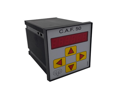
Diagnostics and operation phase displayed on front on module.

Timed adjustment cycle control

Electromechanical relay electrical and mechanical life duration check

Strike anti-repeat control, with possibility of set-up with three key switches for the following operating cycles:
1) by hand for maintenance operations – safety devices off – safety devices on
2) by means of repeat pedal – pedal and buttons (two-hand control)
3) adjustment cycle – single strike – continuous.
Single/continuous operating cycle feature overstroke control.
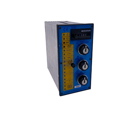
Operation and connections
Controls fitted on front of device.
The pulse-single-continuous switch 20 is used to select the working cycle of the machine.
Pulse operation 17 is used for tuning operations. The machine will only work for a certain pre-set time in this position.
Single strike operation 18 is used to make the machine run a single cycle. Strike repetition will only be possible after fully releasing the buttons and repeating the control. Continuous operation 19 is used to run the machine. After being started, the machine can be stopped by means of the R.P.M.S. or emergency stop buttons.
The continuous pedal-pedal-buttons switch 15 is used to identify the type of device used to start the machine.
Button position 14 enables the push-button panels (the pedal must be off). Position 13 enables the pedal control. Position continuous pedal-continuous 12 enabled continuous machine operation controlled by means of the pedal while the pedal is pressed.
Motor cut-off/die protection TOOL OFF-TOOL ON switch 24 is used for maintenance operations. Position motor cut-off 21 allows the running the brake/clutch unit with the main motor off. Die protection positions TOOL OFF 22 and die protection position TOOL ON 23 respectively deactivate and activate the die efficiency limit switches. Switch 20 will immediately stop the machine while it is running. The machine will immediately stop if controls are released during tool descent. Releasing the controls after BDC will not effect normal operation (continuous-single). Any alarm or emergency will stop the machine. Start controls must be fully released for the machine to repeat a work cycle. Operation of the two control buttons which can be connected to the machine must be synchronised within 0.5 sec. More push-button panels can be connected upon request.
Technical features
√ Power supply 24V +/- 15% a.c.
√ Power consumption about 40VA.
√ The protection fuses 25-26 are included in the appliance.
√ Solenoid valve power supply 220Vmax. Recommended maximum operating frequency 180 cycles / min.
√ The totalizer of the pieces produced is also provided.
√ Appliance front size mm. 96 x 192. Fixing with two tie rods.
Incoming signals
equipment
1 – Pair of buttons for machine start-up (also designed for several couples)
1 – Pedal control or machine control
2 – Stop switch for P.M.S. operating cycle (PROXY 24 V P.N.P.)
2 – Limit switch for mold protection. One of the limit switches must be mounted in correspondence with the specific synchronization cam, the other can be mounted on the machining tool to protect it.
2 – Limit switch for controlling the limit switch.
2 – Contacts that must be closed when the main engine of the machine is running.
1 – Reverse motor contact.
1 – Contact for compressed air pressure switch.
2 – Contacts for safety barriers.
1 – Input to which multiple R. P. M .S buttons can be connected.
1 – Input to which all the emergency contacts can be connected together.
It is mandatory to use emergency keys with mechanical locking.

Signals on the front
of the appliance
1 – It signals the presence of voltage to the equipment.
2 – Each time the mold control is activated, it switches off.
3 – Indicates the presence of air pressure in the pneumatic circuit.
5 – (start) Indicates when a machine cycle start sequence has been completed (e.g. all start buttons have been activated)
7 – (reset occurred) It signals at the end of the working cycle that all the commands have been released and the cycle can be repeated.
10 –Report the intervention of any emergency
11 – Indicates that the safety barrier is in the correct position
16 – Signals that all links and contacts are connected correctly.
8 – It signals the normal operation and connection of the two limit switches of the operating cycle
9 – It switches off when the R.P.M.S.
4 – Indicates the voltage to the solenoid valves (normal operation)
6 – Motor stopped signal, lack of simultaneity on the buttons, on predisposition of buttons 14 with the pedal inserted
17 – In conjunction with the fixed signaling of one of the two cams, it signals the failure of the limit switches of the machine cycle or of the relative connections; signals the imbalance of the solenoid valve and the intervention of the limit switch over-stroke control.
18 – Reset button for when the machine cycle limit switches or the relative connections or solenoid valve unbalance fail (the machine cycle is reset only after having repaired the fault)
27 – Lockable stroke counter reset button
Check out our catalog
STANDARD PRODUCTS
CONTACT US
For any information, question or request for collaboration you can contact us from the contact form.
Our Customer Service will be happy to answer your questions.
[contact-form-7 id=”5″ html_class=”cf7_custom_style_1″]